Learn to Build Alexa Skills & Converse with Machines – Udemy Course in $9.99

I am incredibly excited to launch a course on Udemy related to building Alexa Custom Skills and utilise your Amazon Echo or related devices in a much more powerful way.

Learn Alexa Custom Skills by building your Rad Personal Assistant

The course is available at https://www.udemy.com/build-your-rad-personal-assistant-with-amazon-alexa-custom-skills/?couponCode=ALEXA_9.99USD

Get it for $9.99 ONLY. Use Coupon Code ALEXA_9.99USD


There is a shift happening in the way we as a species communicate with machines. With the advent of Amazon Alexa, Google Assistant, Apple Siri, and Microsoft Cortana, the focus on Voice User Interfaces or Voice Activated Conversational Interfaces is rapidly increasing.

This ever-changing world presents a threat to the way we operate, especially when we do not understand it. A more AI aware world might be years away, but if we learn how to talk to and control the machines then we grow collectively.

The real goal of this course is to get you competent enough to understand the complexities that go behind designing and creating the voice user interfaces so that you can immediately assess how different pieces of the puzzle fit together.

However, no matter how much of the fundamental knowledge you have, if you are unable to put it to practice, then usually it is of no real value. This course on building a personal assistant using Alexa Custom Skills is just one of the techniques, and you will learn very soon that you can design a variety of interfaces through the knowledge that you gain.

By using Amazon Alexa, and building a Voice Activated Personal Assistant, you will gain the following:

  1. Understand what is Amazon Alexa and its ecosystem
  2. What are Voice Interaction Models, and how they can help you build a better and reliable voice interface
  3. Know the technologies that work behind a voice-activated interface
  4. Use Amazon Services such as Lambda, S3, CloudWatch, & IAM and how they interact with each other
  5. Deconstruct an Alexa Skill, and get clarity on what are Intents, Slots, and Utterances
  6. Develop with Node.js and Alexa Skills Kit SDK to build a personal assistant that responds to your queries
  7. Connect with Third Party APIs and process information, use asynchronous requests and callbacks
  8. Maintain data persistence within an Active Alexa Session
  9. Introduce errors, and Test Alexa Skills through 4 different modes including simulators and physical devices
  10. Leverage the Amazon Web Services to build a Consistently Reliable Architecture

Enroll Now, and begin to shape the brand new voice-activated world!

Following is the link. Use Coupon Code DISCOUNTBLOG to get 20% OFF on the list price.

https://www.udemy.com/build-your-rad-personal-assistant-with-amazon-alexa-custom-skills/?couponCode=DISCOUNTBLOG


Transcribe Audio or Video through an offline standalone application (HTML5 based)

I use a Sony TX650 device for recording audio notes. It allows me to increase/decrease the playback speed and helps me in faster transcription. However, it is not always efficient because when doing a transcription on a machine, I need to juggle between the player’s controls as well as the keyboard.

Transcribe Audio or Video Offline

To alleviate that, I created an offline transcription software. It is a single page HTML file and using Javascript and HTML5 Local Storage you can do transcription of both your audio and video files – and export the content.

A demo is available at
https://exain.com/transcribe

and the source code is available on GitHub at
https://github.com/technotablet/transcribe

Create One Time Password (OTP) For Your Applications Using FreeOTP

We typically protect our applications using an identifier (such as a username or email address), and a password. Most organisations have also started to use 2-Factor Authentication (2FA), where apart from a password, you will need to identify yourself through a 2nd medium (such as a password on your phone).

I will demonstrate how you can implement a One Time Password (OTP) based setup which you can use as a 2FA or a standalone setup.

The concept is quite easy to understand:

  1. We will use TOTP (Time based OTP)
  2. Create a Hex Value which will be a user’s key (such as a1b2c3d4e5)
  3. Generate a Base32 encoded version of the key
  4. Install an app FreeOTP in your phone and specify the total OTP digits (6 by default), and the step size in seconds (30 seconds)
  5. Feed in the user’s key, and the Base32 encoded version along with other identifiers such as email address for identification
  6. Now, whenever you use the FreeOTP, you will receive a number valid for 30 seconds (the step size / interval)
  7. Validate the number on the server through oathtool by specifying the digits, the step size, and the Hex Value. It will match.

Let’s get started.


Base Setup

Install oathtool on the server which will do the validation

apt-get install oathtool

Install FreeOTP on your mobile phone. It is a free app available on iOS and Android.

Create a Hex Key

The easiest way is

head -10 /dev/urandom | md5sum | cut -b 1-8

The above command will output an 8-digit Hex Value.

You can create more complicated keys through

head -10 /dev/urandom | md5sum | cut -b 1-30

You can also use a combination of 0-9 digits and a-f alphabets to create the key.

Get a base32 encoded version of the Hex Value

Run the following command

oathtool --totp --verbose YOUR_HEX_KEY

You will see among other items, a “Base32 secret“. Note that value as you will need it to feed into FreeOTP.

FreeOTP Configuration

  1. Enter the Issuer – it is for your reference. Can be an email or anything else.
  2. Enter the Hex Value as ID
  3. Enter the Base32 Value as Secret
  4. Interval is 30 Seconds by default
  5. Digits are 6 by default
  6. Algorithm is SHA1 by default

That’s all. Now save that information, and when you click on your entry, it will show you a number valid for 30 seconds.

OTP Setup using FreeOTP and oathtool


Validate it on the server

Use the command oathtool to validate it on the server

oathtool --totp YOUR_HEX_KEY

The above assumes that you’ve taken the step size (interval) as 30 and digits as 6. If you have done a different configuration, you can try out the following too by specifying the step size and digits explicitly.

oathtool --totp -s 30 -d 6 YOUR_HEX_KEY

(Replace 30 & 6 with your step size & digits respectively)

Next steps

  1. To manage users, you can integrate it with a user database where each user also has a randomly generated key associated with it. Create a QR code with all relevant information (Issuer, ID, Secret) so that FreeOTP can easily read it. Give it to the users to add information to their phones.
  2. At the server end, when you are authenticating a user, ask for a identifier (such as the email address or a username), and use the key associated with that identifier to generate an OTP using the oathtool command. If the one provided by the user matches with the one generated by your system, then you can authenticate the user.
  3. What if 30 seconds is too less and while the user is entering the information, the information changes? You can generate future OTPs by using the time window parameter (-w). You can also use a historical time using the current time parameter (-n). For example:
    oathtool --totp -w 5 -N "2017-08-16 22:46:00" 1a2b3c4d5e

How To Securely Open Ports (SSH, RDP etc.) On-Demand For Dynamic IPs Through iptables

An encrypted SSH connection allows complete access to your machine. However, unless you diligently manage all security updates to your OS and SSH Server, there is a possibility that your SSH server gets compromised.

Typically, system administrators restrict access to the SSH Server (Port 22) to selected IPs. The limitation in opening the Port 22 to selected Static IPs is that you will not be able to connect to it when you are on the move, and need to access your machine from, say a mobile phone.

To overcome this limitation, I have written a script that uses a combination of a web server and iptables firewall, and grants access to Port 22 (or any other Port) on demand to an IP you prefer. It can also work equally well on an AWS EC2 machine where you open Port 22 for all IPs (0.0.0.0/0) using a Security Group, and then restrict access via iptables to that EC2 instance.

I will be using

  • Ubuntu
  • Apache with PHP
  • iptables Firewall
  • sudo Access

Step 1 – Grant Access to iptables to www-data user

On Ubuntu, Apache runs with www-data as a user. We will allow www-data user to execute iptables via sudo without a password

Edit the sudoers file

sudo visudo

At the end of the file, add the following

www-data ALL=NOPASSWD: /sbin/iptables

The line above allows www-data access to the command iptables, without a password.

Verify if sudo is indeed working for www-data user.

Run the following command to verify.

sudo -H -u www-data bash -c 'sudo iptables -L'

Note: It should not ask any password for www-data and show the data related to iptables as shown in the screenshot above.

Step 2 – Allow Authenticated Access to Ports via The Web

We will now create a file that we’ll put on a web server for easy access. Save the following in a file, and place it on a safe, https protected location on your web server.

  1. Get the code at GitHub –https://github.com/technotablet/open-port-dynamically/blob/master/openport.php
  2. Change the password and the port that you wish to open in openport.php

Now access the openport.php script from your browser.

Complete GitHub Repository at https://github.com/technotablet/open-port-dynamically

For example: https://yourdomain.com/openport.php (Replace the URL with your domain & script name)

Maintenance

  1. The ports that you open via the script tend to remain open like forever. You should ideally setup a firewall script via iptables and reset the rules at a pre-defined interval.
  2. Instead of using a fixed password, you can try out an OTP version (tutorial coming soon).
  3. For RDP and other ports that are not on the same machine, but are within the same network, you can setup Port Forwarding based on iptables and do the relevant NAT based redirection.

Use Epson L350 (or L300 / L200 Series Scanner) on Ubuntu 16.04/Linux Mint 18 and above

Credit: http://www.linuxquestions.org/questions/linux-hardware-18/scanner-not-detected-4175578422/ (Pedroski and hazel)

To run Epson L350 Scanner on Ubuntu 16.04 / Linux Mint 18 and above, follow the steps below:
  1. Make sure your Epson L350 Printer is fully functional and is printing the documents. Only the Scanner is not working.
  2. Download the Image Scan! for Linux from http://support.epson.net/linux/en/iscan_c.html
  3. Extract the zip file. Open a console, go into that directory and then run sudo ./install.sh
  4. Connect your printer. In the console, enter “lsusb” command. You should see one of the printers listed. In my setup it was
    Bus 002 Device 006: ID 04b8:08a1 Seiko Epson Corp.
  5. Because you installed iscan, you will now find a new file /etc/sane.d/epkowa.conf available. Edit that file through
    sudo gedit /etc/sane.d/epkowa.conf (You can use xed or vi)
  6. After the line “#usb 0x04b8 0x0110“, enter the line “usb 04b8 08a1“. Save it. (change it based on the device ID you see in lsusb. Note that the colon “:” is no longer there).
  7. In the other /etc/sane.d/epson* files, comment out all lines with a # (or remove those files altogether).
  8. Disconnect the printer, and reconnect. On the console, run sudo scanimage -L and see if the scanner is visible.
  9. Open Simple Scan, and it should scan properly.
Reason why the Scanner is not working is because in Ubuntu 16.04
“SANE requires either a usb vendor/model code or a scanner device created by a kernel module but not both. They interfere with each other. And the kernel scanner module is deprecated now. You’re supposed to use libusb.”.

Use Amazon’s AWS VPC, & Your VPN To Extend Your Server Infrastructure (using Static Routing)

With the invent of cloud computing, a much powerful addition to a corporate data centre was the ability to scale its infrastructure in a virtual private cloud. The setup thus becomes flexible enough to manage the resource demand and remains safe from the public eye.

Using AWS VPC with Corporate VPN is an excellent option to extend a corporate data centre.

  • AWS offers multiple regions and extreme flexibility to tweak your infrastructure needs
  • The data rides on a VPN Tunnel and is not publicly exposed, thus meeting information security & confidentiality needs of an organisation

In the following post, I will delve deeper into creating a prototype of how you can extend your business network and put it on the “cloud”.

What we will be doing:

  1. Setup VPC & VPN on AWS
  2. Configure an External Machine to act as Corporate IPsec VPN (using “racoon”)
  3. Connect our External Machine to AWS and test

Note: We will use “Static” routing, which is simpler, and not “Dynamic (BGP)” routing, which requires many more steps.

AWSVPN-VPN Architecture

Interconnecting AWS VPC & VPN with Corporate VPN through IPSec (racoon)


Our Base Setup

  1. An External Machine to act as a Corporate VPN Appliance (referred as “CorpVPN”), running Ubuntu/Debian Linux variant with a public IP. I took a cloud server with Rackspace Cloud, but you can take it up on AWS in a different region too if you prefer.
  2. Opening of UDP 500 & UDP 4500 on the CorpVPN Firewall (or AWS Security Group Inbound Rule if you’re using AWS EC2 machine as CorpVPN Appliance).
  3. Since CorpVPN is an independent device, we don’t have a connecting internal network to it. So we will use the Link-local 169.254.x.x IP Addresses.
  4. An AWS Account where we can create an EC2 machine and configure VPN Services


Part 1 – AWS Setup

1a) VPC Configuration

Create a New VPC

Select “VPC” option under Services

Go to “Your VPCs”, and “Create New” VPC

AWSVPN-Setup of VPC 02

We will use the network as 172.28.0.0/16 for the EC2 Machines which will work as our extended network.

Create a Subnet for your EC2 Machines. We will select it when we configure our EC2 Machine. In this example, we use 172.28.16.0/24 as the subnet.

AWSVPN-Setup Subnet

Add an Internet Gateway

Create an Internet Gateway and attach it with the new VPC that you created so that your EC2 machines can reach Internet & you can connect to them remotely. You can let go of this option if you don’t want any external connectivity.

AWSVPN-Setup Internet Gateway 01AWSVPN-Setup Internet Gateway 02AWSVPN-Setup Routing

Setup a Security Group

Create a Security Group that allows ping and SSH to your EC2 machines. As per your preference, open ICMP and SSH for everyone or only to limited IP addresses.

AWSVPN-Create Security Group 01AWSVPN-Setup Security Group 02

1b) VPN Configuration

Customer Gateway (CGW)

The Customer Gateway is primarily our CorpVPN gateway. We need to provide the IP Address of our CorpVPN server. If you have it readily available, then provide it, else add a random IP and change later once your CorpVPN server is setup.

AWSVPN-Setup Customer Gateway

We will use as an example 100.101.102.103 as the IP of the CorpVPN Server. Please note that “Static” routing is selected.

Virtual Private Gateway (VGW)

We create a Virtual Private Gateway that enables network connectivity to our VPC. It is a two step process

  • We create the VGW
  • We attach it to our VPC that we created

AWSVPN-Setup Virtual Private Gateway 01AWSVPN-Setup Virtual Private Gateway 02

VPN Connection

It is a hardware VPN and is a paid service. Create a new VPN and select the following

  • VGW that you created before
  • CGW that you created before
AWSVPN-Setup VPN Connection 01

Routing Option should be “Static”

AWSVPN-Setup VPN Connection 02


Static IP Prefixes will be Link-local addresses 169.254.0.0/16. It means you will reach the AWS network through your Private IP Address in 169.254.x.x series.

Note: We are using the above configuration because we have an independent CorpVPN machine. If you do have a VPN appliance and a network behind it, please go ahead and use your internal IP range.

It takes a few minutes to get the VPN ready.

Once the VPN is available, you can download the “Generic” configuration. It is a text file with the VPN IP Addresses and other configuration details.

AWSVPN-Sample Tunnel Config

Example Tunnel #1 Configuration’s Text File

Enable Route Propagation

Open the “Route Table”, select the “Route Propagation” tab. For the CorpVPN VGW, enable “Propagate”.

AWSVPN-Route Propagation

It is a critical step. Without “Route Propagation”, you will not be able to reach the EC2 machines from the VPN.

1c) EC2 Machine Setup

In the same region where you have setup your VPN, create an EC2 machine. I used t2.nano with Ubuntu 16.04. This EC2 machine will act as our extended network hosted on AWS.

Please ensure that you select the VPC that we created when configuring the EC2 instance.

AWSVPN-EC2 Machine Setup 01

Also, ensure that you select the Security Group that we created for the Corporate VPC.

AWSVPN-EC2 Machine Setup 02


Part 2 – CorpVPN Setup (the CGW Setup)

Points to note:

  • AWS VPN Setup by default provides 2 VPN Tunnels (for Failover). However, since we are just testing it out, we will only be using 1 Tunnel. It will help ease the setup.
  • The CorpVPN setup is our Customer Gateway, and we had provided its IP address while configuring the VPN in AWS.
  • Remember – we are using a separate server (hosted on Rackspace Cloud) to act as CorpVPN Appliance. You can use an AWS Setup also by setting up an Ubuntu based server in a different region. Don’t forget to open UDP 500 & UDP 4500 in the Security Group / Firewall.

2a) Base Installation for IPsec & Racoon VPN Server

Install ipsec-tools & racoon. On a Debian/Ubuntu machine, you can use

apt-get install ipsec-tools racoon

Racoon is the IPsec server that we will use to establish the VPN. We will also use ipsec-tools to setup the SPD (Security Policy Database) to allow connection to-and-from AWS.

2b) IPsec Tools Configuration

Modify the file /etc/ipsec-tools.conf and use the entries below. You will need to refer to the “Generic Configuration” that you downloaded in the steps above from AWS interface.

To be specific, the IP Addresses as mentioned in our downloaded configuration are:

  • CGW Inside IP – 169.254.54.122/30 (At Customer/CorpVPN’s end)
  • VGW Inside IP – 169.254.54.121/30 (At AWS End)


  • CGW Outside IP – 100.101.102.103 (CorpVPN’s publicly exposed IP)
  • VGW Outside IP – 35.154.122.65 (For Tunnel #1, it is AWS VPN IP)


/etc/ipsec-tools.conf

#!/usr/sbin/setkey -f

## Flush the SAD and SPD
flush;
spdflush;


# Tunnel 1
# -4 means use only IPv4. Can be omitted.
# a) Allow CGW Inside IP Address to VGW Inside IP Address "outbound" from CGW Outside IP Address to VGW Outside IP Address
spdadd -4 169.254.54.122/30 169.254.54.121/30 any -P out ipsec esp/tunnel/101.102.103.104-35.154.122.65/require;
# b) Allow VGW Inside IP Address to CGW Inside IP Address "inbound" from VGW Outside IP Address to CGW Outside IP Address
spdadd -4 169.254.54.121/30 169.254.54.122/30 any -P in ipsec esp/tunnel/35.154.122.65-101.102.103.104/require;


# c) Allow CGW Inside IP Address to VPC Network "outbound" from CGW Outside IP Address to VGW Outside IP Address
spdadd -4 169.254.54.122/30 172.28.0.0/16 any -P out ipsec esp/tunnel/101.102.103.104-35.154.122.65/require;
# d) Allow VPC Network to CGW Inside IP Address "inbound" from VGW Outside IP Address to CGW Outside IP Address
spdadd -4 172.28.0.0/16 169.254.54.122/30 any -P in ipsec esp/tunnel/35.154.122.65-101.102.103.104/require;

Now on the CorpVPN setup, we will add the CGW Inside IP

ip a a 169.254.54.122/30 dev eth0

Replace eth0 with the relevant network card, preferably the one on which you have configured the CorpVPN/CGW IP.
Later, if you need to delete it, you can use ip a d 169.254.54.122/30 dev eth0

Do a

route -n

To confirm if the IP is now available in the routing table.

Reset the ipsec-tools rules

/etc/init.d/setkey restart

2c) Racoon Configuration

We will now setup the IPsec Server – Racoon. The configuration is simple, and you can copy paste the following and replace the IPs with your relevant IP Address Ranges.

Modify the file /etc/racoon/racoon.conf

path pre_shared_key "/etc/racoon/psk.txt";

# Tunnel 1
# VGW Outside IP Address
remote 35.154.122.65
{
     exchange_mode main;
     # CGW Outside IP Address
     my_identifier address 101.102.103.104; 
     # VGW Outside IP Address
     peers_identifier address 35.154.122.65;
     ike_frag on;
     generate_policy = off;
     initial_contact = on;
     nat_traversal = on;

     dpd_delay = 10;
     dpd_maxfail = 3;
     support_proxy on;
     proposal_check claim;

     proposal
     {
          authentication_method pre_shared_key;
          encryption_algorithm aes 128;
          hash_algorithm sha1;
          dh_group 2;
          lifetime time 28800 secs;
     }
}


# CGW Inside IP Address & VGW Inside IP Address
sainfo address 169.254.54.122/30 any address 169.254.54.121/30 any
{
     encryption_algorithm aes 128;
     authentication_algorithm hmac_sha1;
     pfs_group 2;
     lifetime time 3600 secs;
     compression_algorithm deflate;
}


In /etc/racoon/psk.txt, enter the VGW Outside IP Address, and the Pre-Shared Key that is available in the configuration.

35.154.122.65    pjt61xwU3jRoNiUBXVli73aQs31awm4Gg


Restart Racoon.

  • To begin with, you can do a debug mode ON racoon initialisation. For example:
racoon -Fvdd
  • Later on, you can just manage it through init script.
/etc/init.d/racoon restart

Part 3 – Testing the setup

Now you need to ping your VGW Inside IP Address from your CorpVPN/CGW machine

ping 169.254.54.121

It should start pinging within a few seconds.

You should be able to see the status of the VPN Tunnel as up for your VGW Outside IP Address under VPN Connections on Amazon. It is important for this to happen.

AWSVPN-Tunnel UP

If the above doesn’t work, please refer to the Troubleshooting section.

Now you need to add a route so that you can reach your 172.28.0.0/16 range of IP Addresses.

route add -net 172.28.0.0/16 gw 169.254.54.121 dev eth0

Do a

route -n

To check if your configuration is correct, and you have set the appropriate gateway.

Now ping your EC2 instance’s Private IP address.

ping 172.28.16.136

It should work.

Similarly, from your AWS EC2 instance, you can ping the CGW Inside IP Address

ping 169.254.54.122

If it works, then CONGRATULATIONS to you. You have successfully established the two way connection.


Part 4 – Maintenance & Troubleshooting

To make it permanent, you need to add the ip address addition (of CGW Inside IP Address), and routing rules (Using VGW Inside IP Address as Gateway for 172.28.0.0/16 range) in maybe /etc/rc.local or in your /etc/network/interfaces so that they apply automatically on a reboot.

Also, to keep the tunnel alive, traffic has to pass through it. You can setup a cron job with the following to ensure that the tunnel is always up

* * * * * (/bin/ping -c 10 169.254.54.121) > /dev/null 2>&1

You have to be able to ping the inside IP Address of VGW. If that is not happening, please make sure you have done ‘Route Propagation’ for that VGW under ‘Routing Tables’ -> ‘Route Propagation’ under AWS VPC Settings.

You should be able to ping your EC2 instance. If not, then

  • Make sure you’ve allowed ICMP (ping packets) to pass through in the Firewall (Security Group for your EC2 Instance).
  • You have added the route on your CGW, for reaching your EC2 Subnet (172.16.x.x series for example) through your VGW Inside IP Address (as mentioned in the tutorial above).
  • Have you replaced the IP addresses with the ones provided in the Downloaded Configuration File as well as the ones of your Customer Gateway?

If the tunnel works but goes down intermittently, then to keep it active you need to ping the VGW Inside IP Address continuously. Use a cron job for that as explained in the tutorial above.

That’s all. There are instructions on AWS to setup through dedicated VPN Appliances. You can refer those to Extend Your Network and make it more scalable.

Fitbit Detailed Heart Rate Data Tracking – Intraday

I recently upgraded to Fitbit Alta HR. It is much better than Fitbit Flex that I had been using for past many years. And the best part is the heart rate tracking, which also helps in getting better Sleep Quality outputs.

Fitbit Alta HR captures Heart Rate periodically (at few second intervals)

What was missing?

However, one thing that I missed with Alta HR and the Fitbit App was the display of the Heart Rate data. For instance, below is my Heart Rate during an Emotionally Charged Up Environment at Workplace. Note, I was sitting with No Physical Activity!

Heartbeat - Emotionally Charged

Heart Rate Variation while sitting – but with Emotions Running High!

If you notice, the Fitbit App shows Heart Rate data in 5-minute intervals. And the self-quantification person that I am, that was not enough. I wanted the entire data that Alta HR recorded. Thus, I began working on getting that reliably.


The End Result, & How You Can Use It

I have created a web version where you can review your Heart Rate data quickly.

Get your Heart Rate Chart at https://exain.com/fitbit

Remember to see the Tutorial on how to retrieve your “Client ID” from the Fitbit website.

Note: The application I have created saves the heart rate data in a database. It means that I will have your heart rate data. However, I am not asking for or collecting any user information. So despite the fact that I have the heart rate data, I cannot link it with an individual.

I have open sourced the entire code, and it is available on GitHub.

https://github.com/technotablet/fitbit

How it works

  • Fitbit allows developers to connect to its API after authentication through the OAuth2 Protocol.
  • Since the heart rate data is personal to a user, Fitbit does not permit third party developers to access heart rate data of another user.
  • You will need to authenticate yourself on the Fitbit Developer Portal and create an “App” on it. It is a relatively simple process, and if you are connecting to my service at https://exain.com/fitbit, then you can view the tutorial on YouTube.

Now Go – Track your HB!

Port Forwarding in AWS LightSail or EC2 machines via SSH

I have a Smart Lighting system at home powered by Philips Hue. I was trying to connect to my Philips Hue Bridge’s IP remotely without implementing Port Forwarding on my WiFi Router.

Instead of setting up an EC2 instance, I moved ahead with a Lightsail instance, which unlike EC2, is much less complicated, and also provides the download of private key, the firewall changes etc. upfront for easy and convenient access.

Disclaimer: The process I mention below may not be optimum if you are opening up sensitive/unprotected ports without appropriate security measures. Use your own judgement before you implement Port Forwarding.

Following is an example of what I planned to do. Basically, I wanted to access Port 9090 on my Lightsail instance to reach the Philips Hue Bridge at my home.

Port Forwarding Setup using AWS Lightsail/EC2

  • I had opened Port 9090 through the Firewall option in Lightsail
  • I also had set a password for root user by using the command sudo passwd

However, the port forwarding did not work because Lightsail’s SSH does not support port forwarding by default.

I made the following changes in /etc/ssh/sshd_config to enable port forwarding.

# Changed the following line
PermitRootLogin yes

# Added at the bottom the following
UseDNS no

ClientAliveInterval 180
ClientAliveCountMax 3

GatewayPorts yes

Then I restarted ssh using root

/etc/init.d/ssh restart

After that I was able to do the port forwarding smoothly by executing the following command on my Desktop at home (your needs may vary, so modify accordingly)

ssh -i key.pem -R *:9090:192.168.0.75:80 root@101.102.103.104

Now from a remote machine, if I reach out to Port 9090 on 101.102.103.104, it works well. The command man ssh will help you understand the -L (Local Forward to Remote) & -R (Remote Forward to Local) option better. You can also use PuTTY to implement Port Forwarding.

Amazon RDS Multi-AZ Setup Failover Simulation

I had setup an Amazon RDS MySQL instance with Multi-AZ option turned on. However, I couldn’t test if the Multi-AZ setup was working as expected. Thus, I prepared the test cases below to simulate a downtime and verify if the Failover worked and the servers switched places.

I am assuming you have already setup a Multi-AZ RDS instance for MySQL. If not, check out http://docs.aws.amazon.com/AmazonRDS/latest/UserGuide/CHAP_GettingStarted.CreatingConnecting.MySQL.html

How will we test it?

  1. Identify the two servers that AWS allocates to us (Primary & Secondary)
  2. Start adding data/load test one of the servers and do a reboot of that server to simulate a downtime.
  3. Review if the switchover happened, and the data consistency.

Base Setup

  1. Multi-AZ MySQL installation (db.t2.micro) in Mumbai Location (AP-South-1)
  2. Ubuntu EC2 Instance (t2.nano) in Mumbai Location (AP-South-1)
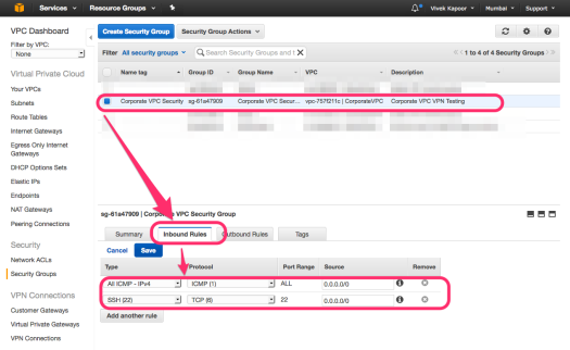
  3. Security Group Changes to allow access to the incoming port 3306 from the internal IP address of the EC2 instance.
AWSRDS-Security Group

Security Group Settings • 172.31.28.190 is the IP Address of the EC2 instance


Determine Primary & Secondary Zone IPs for your RDS instance

In Amazon RDS with a Multi-AZ setup, there are two availability zones within a location. Primary Availability Zone (referred as Availability Zone) & Secondary Availability Zone (Referred as Secondary Zone).

The purpose of Multi-AZ setup is that your database setup is running on an automatic failover environment with a realtime replicated standby server. In case the primary server goes down, the secondary server can elevate itself to primary and continue the services. Refer https://aws.amazon.com/rds/faqs/#129 and https://aws.amazon.com/rds/details/multi-az/

AWSRDS-RDS Details

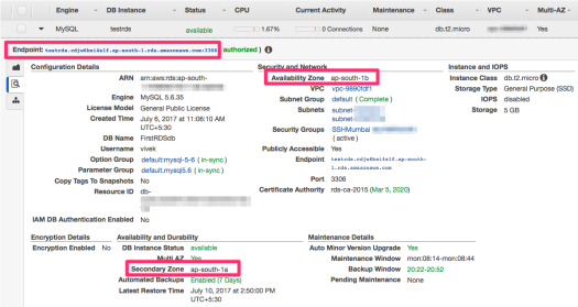
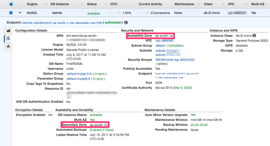
Endpoints & Availability Zones in RDS

Amazon RDS provides you with an Endpoint, which is a domain that you use as your hostname, and connect to your MySQL instance on Port 3306.

The Endpoint is a DNS CNAME that points at a time to one of the two instances available in the different availability zones (Primary & Secondary) with a TTL of 5 Seconds. The first step that we will follow would be to determine what are these two instances, and whether the availability zone has changed successfully.

Note that the Availability Zone currently is ap-south-1b (as in the screenshot above), and the Secondary Zone is ap-south-1a.

For our reference, we’ll use testrds.cdjw6bxi4s1f.ap-south-1.rds.amazonaws.com as the Endpoint that we have. Yours will of course vary.

On your EC2 terminal, run the following

while true; do host testrds.cdjw6bxi4s1f.ap-south-1.rds.amazonaws.com | grep alias ; sleep 1; done

(you can exit using CTRL+C at any point of time)

The above script will continue to check via DNS the pointer to testrds.cdjw6bxi4s1f.ap-south-1.rds.amazonaws.com Endpoint. The result will be something like the following

testrds.cdjw6bxi4s1f.ap-south-1.rds.amazonaws.com is an alias for ec2-13-126-202-244.ap-south-1.compute.amazonaws.com.

Note the alias name ec2-13-126-202-244.ap-south-1.compute.amazonaws.com.

It is the server that is running MySQL instance, and your scripts will connect to eventually. It is the MySQL server for ap-south-1b zone assigned to your instance.

Now let’s simulate a scenario through reboot where we will make the Secondary Zone the Primary.

  • From your AWS console, select the DB Instance, and under Instance Options, select “Reboot”.
AWSRDS-Reboot Instance

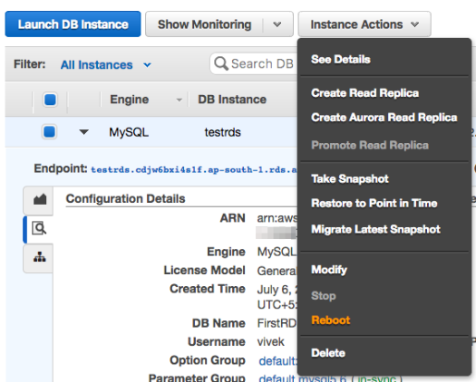
Rebooting RDS DB Instance

  • Under the Reboot options, select the option “Reboot With Failover?”, and click Reboot.
AWSRDS-Reboot Option

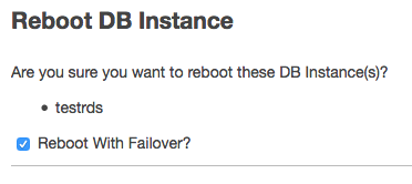
Reboot With Failover option

  • Continue to monitor the terminal where you were checking the domain name pointing for your Endpoint.
AWSRDS-RDS Endpoint DNS Change

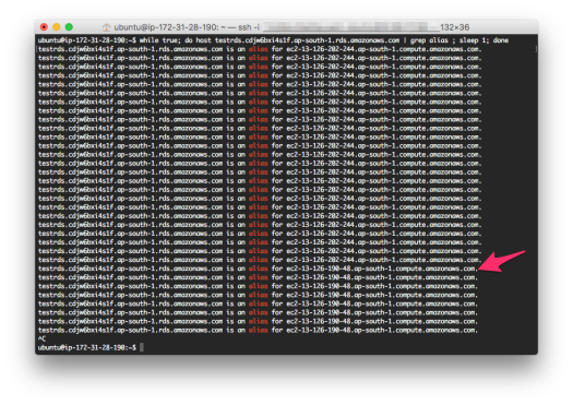
Endpoint’s DNS Alias Changes on Server Switching

It takes <60 seconds for the Endpoint DNS information to change. You will be able to see a new domain name that your endpoint is now pointing towards.

testrds.cdjw6bxi4s1f.ap-south-1.rds.amazonaws.com is an alias for ec2-13-126-190-48.ap-south-1.compute.amazonaws.com.

You can refresh the AWS console. It takes within a few seconds to <10 minutes to see the updated Availability Zone information on the AWS console.

AWSRDS-RDS Details Zone Change

Availability Zone Switchover successful

If you notice, the Availability Zone has now become ap-south-1a (instead of 1b), and Secondary Zone is now ap-south-1b (instead of 1a). Hence the servers have interchanged, and now you can connect only to the Primary Server.

Results for the above setup (your information will vary):

  • ap-south-1a is pointing to ec2-13-126-190-48.ap-south-1.compute.amazonaws.com.
  • ap-south-1b is pointing to ec2-13-126-202-244.ap-south-1.compute.amazonaws.com.

Note: You can only connect to one of the servers at a time, and that is the Primary Availability Zone server.


Testing Multi-AZ Failover

Referring to https://aws.amazon.com/rds/details/multi-az/, the Multi-AZ failover mode works in a synchronous Master/Slave relationship. There are two servers running simultaneously, the Primary one is accessible to end user, and the data is replicated in real time to a Secondary server (residing in a different zone), which is not accessible to the end user.

In case of a Primary Server’s unavailability, the Secondary Zone’s server is elevated to be the Primary, and hence accessible to the end user and application.

Test Case 1 – We’ll keep on connecting to the database and inserting one record every time in the database. The purpose is to check how much time does it take for the failover to happen. Basically Primary Availability Zone will become Secondary Availability Zone, and vice versa.

Test Case 2 – We’ll connect to the Primary Zone’s Instance directly (instead of using the Endpoint provided) and start adding the data through multiple clients. While the data is being added, we’ll reboot the machine with Failover mode on. It will make the Primary Zone secondary and inaccessible, and the Secondary Zone will now be made Primary. We will then verify the data insertion that we did on the now Secondary server, and if all records are available on the now Primary server.

I will use basic PHP scripting to test out the Failover capacity and if the data is replicated correctly. You can replicate it in any other language that you prefer.

  • Install PHP & MySQL client
apt-get install mysql-client-core-5.6 php5-cli php5-mysql
  • Connect to MySQL, and create a table in the MySQL Database (please replace the values based on your environment)
 mysql -h testrds.cdjw6bxi4s1f.ap-south-1.rds.amazonaws.com -u vivek -p FirstRDSdb
CREATE TABLE `failover_test` (
 `id` int(10) unsigned NOT NULL AUTO_INCREMENT,
 `cycle` varchar(50) DEFAULT NULL,
 `counter` int(10) unsigned NOT NULL,
 `failover_date` datetime NOT NULL,
 PRIMARY KEY (`id`)
 ) ENGINE=InnoDB AUTO_INCREMENT=1 DEFAULT CHARSET=latin1 COMMENT='AWS RDS Failover Testing';


Test Case 1 Implementation

Create a PHP script named failover_test.php with the following content

<?php

$host = "testrds.cdjw6bxi4s1f.ap-south-1.rds.amazonaws.com"; // AWS Endpoint
$user = "vivek";
$password = "password";
$dbname = "FirstRDSdb";

if (!isset($argv[1])) {
 exit("Provide a cycle name\n");
}
if (!isset($argv[2])) {
 exit("Provide the id value (that will be coming from for loop)\n");
}
$cycle = $argv[1];
$count = $argv[2];


$conn = mysqli_connect("$host","$user","$password","$dbname");
$q = mysqli_query($conn, "insert into failover_test set cycle='$cycle',counter='$count',failover_date=now() ");

if (!$q) {
 $date = date("Y-m-d H:i:s");
 echo "\n----------- NOT INSERTED $count / $date --------------\n";
} else {
 echo "$count.";
}

mysqli_close($conn);
?>

Action Plan

  1. We will execute the above PHP script in a loop.
  2. While the terminal is executing the script, we will reboot the database with the option ‘Reboot with Failover?‘.
  3. We will monitor the PHP script and notice any numbers that are missing. The count of the missing numbers will give you the total downtime in seconds (approximately).

On your EC2 machine, from the same location where you saved your PHP script, run the following bash command from the terminal

for i in {1..5000}; do timeout 1 php failover_test.php cycle0 $i ; done

(You can use CTRL+C to terminate if you see any errors, or once your work/testing is over)

The above script does entry from 1 to 5000 (or increase it if the number is getting exhausted before you are able to do the testing) in the database. The “timeout” command is there to ensure that if there is no response for 1 second, the script will timeout & exit.

Now move on to the AWS console, and reboot the database instance with the option “Reboot With Failover?” selected.

AWSRDS-Reboot Option

Reboot with Failover option

Continue to monitor the script that is being executed.

AWSRDS-Test1 Downtime

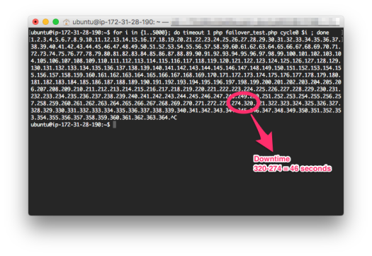
Calculating the Downtime. Use CTRL+C to end the script execution.

Note the duration where the data insertion pauses and no numbers are displayed. It means the Primary Zone’s server has shutdown, and your EC2 instance cannot connect to any RDS server. Once the numbers start showing up again after the delay, it refers to the server in the Secondary Zone now made primary. Note the total missing numbers; their count will tell you about the approximate seconds of total downtime that you faced.


Test Case 2

In this test, we will connect with only the Primary instance and flood it with data. We will then do a reboot and make the Secondary instance Primary. The aim is to test whether the data that was saved in Primary instance is correctly replicated to the Secondary.

Create a new PHP Script failover_load.php

<?php

// You need to get the relevant servers for your testing through
// monitoring DNS changes as I mentioned in the document above
$zoneA = "ec2-13-126-190-48.ap-south-1.compute.amazonaws.com.";
$zoneB = "ec2-13-126-202-244.ap-south-1.compute.amazonaws.com.";

// FOLLOWING IS VERY IMPORTANT
// Select the zone that is currently primary - so that your script can connect to it
// You can get this information from the AWS Console for your DB Instance
$host = $zoneB;
$user = "vivek";
$password = "password";
$dbname = "FirstRDSdb";

if (!isset($argv[1])) {
 exit("Provide a cycle name\n");
}
$cycle = $argv[1];

$link = mysqli_init();

$conn = mysqli_connect("$host","$user","$password","$dbname");

for($count=1;$count<1000000;$count++) {

 $q = mysqli_query($conn, "insert into failover_test set cycle='$cycle',counter='$count',failover_date=now()");
 echo "$count.";

}

?>

Action Plan

  1. We will open 5 terminal windows and execute the above script 5 times, with different cycle names for differentiation
  2. While the scripts are being executed, we will reboot the Database instance with “Reboot with Failover?” option checked.
  3. Once the scripts stop adding further data, we’ll take the max numbers entered, and match it with the database records.

Open 5 terminal windows and connect to your EC2 instance, and prepare the execution of the failover_load.php script with different cycle names (just for identification).

AWSRDS-Prepare RDS Load Test

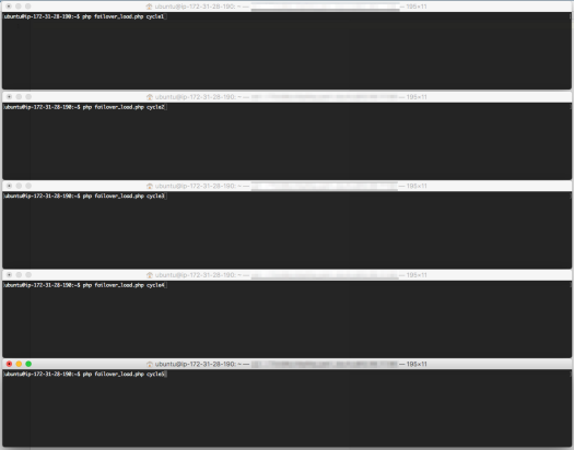
5 separate terminal windows, with different cycle names. Prepared for execution.

Now, execute one by one each of the commands. The faster you do, the better. While the data entry is being done, you can visit the AWS console, and reboot the DB instance with the option “Reboot with Failover?” option selected.

AWSRDS-Reboot Option

Reboot with Failover option

Why did we do this?

The purpose is to add data rapidly in the RDS database, and while the data is being written, we’ll reboot the database instance and make the ‘Secondary Zone’ the ‘Primary’. Since we connected directly to the RDS instance in the Primary Zone (ec2-13-126-202-244.ap-south-1.compute.amazonaws.com.) instead of using the default AWS provided endpoint (testrds.cdjw6bxi4s1f.ap-south-1.rds.amazonaws.com), as soon as the reboot is done, the server that we are inserting data in will stop responding.

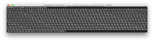
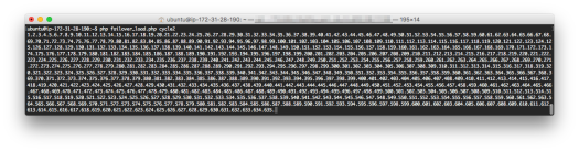
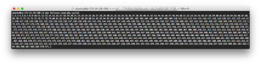
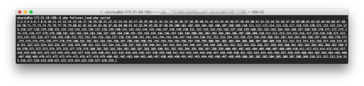
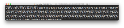
You can see by referring to the screen below, the insertions stopped at the following numbers for each cycle

  • cycle1 – 681
  • cycle2 – 635
  • cycle3 – 571
  • cycle4 – 529
  • cycle5 – 490
AWSRDS-Load Test Cycle1

For Cycle1 – 681

AWSRDS-Load Test Cycle2

For Cycle2 – 635

AWSRDS-Load Test Cycle3

For Cycle3 – 571

AWSRDS-Load Test Cycle4

For Cycle4 – 529

AWSRDS-Load Test Cycle5

For Cycle5 – 490


We have already rebooted the database server, and now we have a new Primary Server.
We will connect to it using the mysql client from our EC2 machine, and run the following queries

ubuntu@ip-172-31-28-190:~$ mysql -h ec2-13-126-190-48.ap-south-1.compute.amazonaws.com. -u vivek FirstRDSdb -p
mysql>
mysql> select max(counter ) from failover_test where cycle='cycle1';
 +---------------+
 | max(counter ) |
 +---------------+
 | 681 |
 +---------------+
 1 row in set (0.01 sec)

mysql> select max(counter ) from failover_test where cycle='cycle2';
 +---------------+
 | max(counter ) |
 +---------------+
 | 635 |
 +---------------+
 1 row in set (0.01 sec)

mysql> select max(counter ) from failover_test where cycle='cycle3';
 +---------------+
 | max(counter ) |
 +---------------+
 | 571 |
 +---------------+
 1 row in set (0.01 sec)

mysql> select max(counter ) from failover_test where cycle='cycle4';
 +---------------+
 | max(counter ) |
 +---------------+
 | 529 |
 +---------------+
 1 row in set (0.01 sec)

mysql> select max(counter ) from failover_test where cycle='cycle5';
 +---------------+
 | max(counter ) |
 +---------------+
 | 490 |
 +---------------+
 1 row in set (0.01 sec)

If you notice, from the above, the relevant counter numbers match from what we saw while we were adding the data using the failover_load.php script.

What we can infer from the test results above is:

  • MySQL does synchronous Primary/Slave replication
  • If Primary Server goes down, the Secondary Server is made primary, and all the data available on Primary is replicated on Secondary and the services can continue to operate
  • You can connect only to the Primary Server at a time


I believe the above is a fairly good implementation and we are able to simulate the failover setup. However, since the system is doing a clean reboot, the data is synchronised properly. A better test would have been to abruptly shutdown the database (due to hardware failure), and review how reliably and swiftly it did the failover.

7 Reasons for UX #FAIL in Enterprise Software

It is nearly impossible to have a good UX consistently in an enterprise software.

That is a strong statement and I’d love to be proved wrong. I come from a background where I developed applications within an enterprise with a defined target audience. I also did software that was available publicly on the Internet. For more than 15 years now, I’ve seen all sides of the table by being both a developer and end user.

First, What works well for Non-Enterprise Software

When you create a software for general public consumption, following is what aids you:

  1. Clarity of Thought. You and your team have planned it out and immersed yourself in it. You know what needs to be done and are focused towards the goal.
  2. Passion. Not only the design & development team, but even stakeholders or subject matter experts are passionate about the software and what’s being built.
  3. Authority. It is for the general public, and you have the authority to take decisions which you think are in the best interest of everyone.
  4. Innovation. That’s the buzzword. You want to innovate and so does everyone else in your team.
  5. Focus. Your focus is to create an Awesome User Experience, period.
  6. Analytics. You measure the usage, and you know what’s working and what isn’t. That impacts the further development, and the evolution continues.

And thus you have a software which you are proud of, and you don’t hesitate to modify it because you know that incremental innovations would always enhance the user experience. Take any top rated app on the App Store, and you would know that this method is what made them successful: Build-Measure-Learn—Repeat

Enterprises? What a #FAIL

The same gleamy eyed UX expert, who built software for the masses and totally, totally inspired from the UX revolution happening around the globe, stumbles, and more often than not fails badly in an enterprise setup. The leading 7 causes are:

  1. Target Audience. This is considered a blessing – you know your users in detail, which systems they have access to, and intelligently design your solution around them. Wrong. You have a fundamental flaw: The audience that you are looking at are deeply uninterested in what you are trying to build. You shouldn’t expect any excitement from them except the key people.
  2. Burden Factor. Unlike an app that the users download from App Store with free will & interest, an enterprise software is forced upon them. How many of you would like to fill in your time sheets, or apply for leaves through a portal – every day?
  3. Resistance. Legacy application being upgraded? There would be resistance, everywhere. Bad karma for you again.
  4. Bottom Line. A good UX process not only requires significant time investment, but good money too. Not many organisations would want to invest in it as the immediate results are always intangible.
  5. Authority & Stake Holders. If the stake holders do not believe in UX and its importance, then they’ll just sign it off. No approval, and no go-ahead. Also, despite a large user base, they are usually the ones who are the owners and speak for others – and thus it is imperative for them to believe in it.
  6. Features First, UX Second. All that matters are the Features – measurable, tangible and objective; the UX is always subjective, and often confused with design and visualisation. The Target Audience also have their wishlist and thus the features reign supreme. This may not be a cause of concern when the software is built the first time – but future updates and iterations can twist it in a way that the UX focus would go for a toss.
  7. Training Costs. Any new software deployment or a visual change is accompanied with a training across the organisation. It leads to reduced productivity, increase in complaints and overall costs – thus most prefer to avoid it.

It is often too late when the lack of good UX is realised. The people change, and their replacements want to maintain the status quo and thus nothing really changes. And eventually only features are added by the developers, and visual design done by the designers based on what seems appropriate to the stakeholders.

Tackling the UX in Enterprise Software

All is not lost, but I’d admit it is not easy. The Enterprise UX 2016 (http://enterpriseux.net/) aims to create a better and sustainable environment, and I wish them luck. However, following are my few cents.

  1. Right People. It can make all the difference. Someone who can develop AND understands design AND understand interacting with customers and gauging their needs might be able to get it right.
  2. Compromise for Flexibility. Assume that the UX might change in the future, and more features put in the system. Thus the UX shouldn’t always be the holy-grail, but rather flexible to incorporate future features.
  3. Transition Plan. Create something like a ‘beta’ preview so that the early adopters can experiment and rollback to the stable version if it doesn’t meet the needs. All new users should be on the new interface, and the older ones slowly transitioned.
  4. Luck. That you get the right Stakeholders who believe in UX. I’ve been lucky on many occasions, and that has helped significantly.
  5. Complete Package. Always demonstrate the solution rendered well – including UX and design (and not just wireframes), and preferably with the right content. That creates much more impact, and can help out with getting the Stakeholders on board for UX.

Apparently, there are more who share the same sentiments. Uday Gajendar in his post Why I design enterprise UX, and you should too! is quite optimistic, and I guess that’s the way to be.

What has been your experience in creating an Enterprise Focused Software, and how much of a role has UX played in it?